Overview Details Technical Results
Propulsion Systems & Cryogenics

LOX/RP-1 Propellant Level Sensor

A cryo-compatible capacitance-based liquid level sensor built for CU Boulder’s Sounding Rocket Lab (SRL) test stand.

2021 – 2022
CU Boulder • SRL
Solo Project

Project Overview

Propellant level sensor comparison and prototype
Prototype concentric-rod capacitance sensor assembly

Mission

Design and build a robust liquid level sensor to measure LOX and RP-1 levels in SRL’s liquid engine test stand tanks. The instrument needed to survive the high-pressure environment and cryogenic temperatures while providing a simple, reliable output for stand operations.

Challenge

Create a capacitance-based measurement that works across fluids with very different permittivities, functions in cryogenic and ambient water test conditions, and fits within SRL’s existing DAQ/control loop without adding system complexity.

Solution

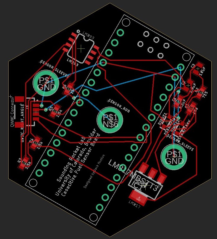
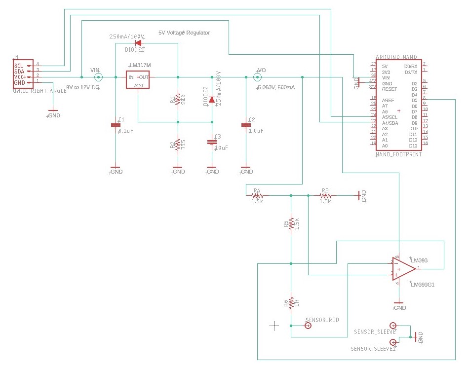
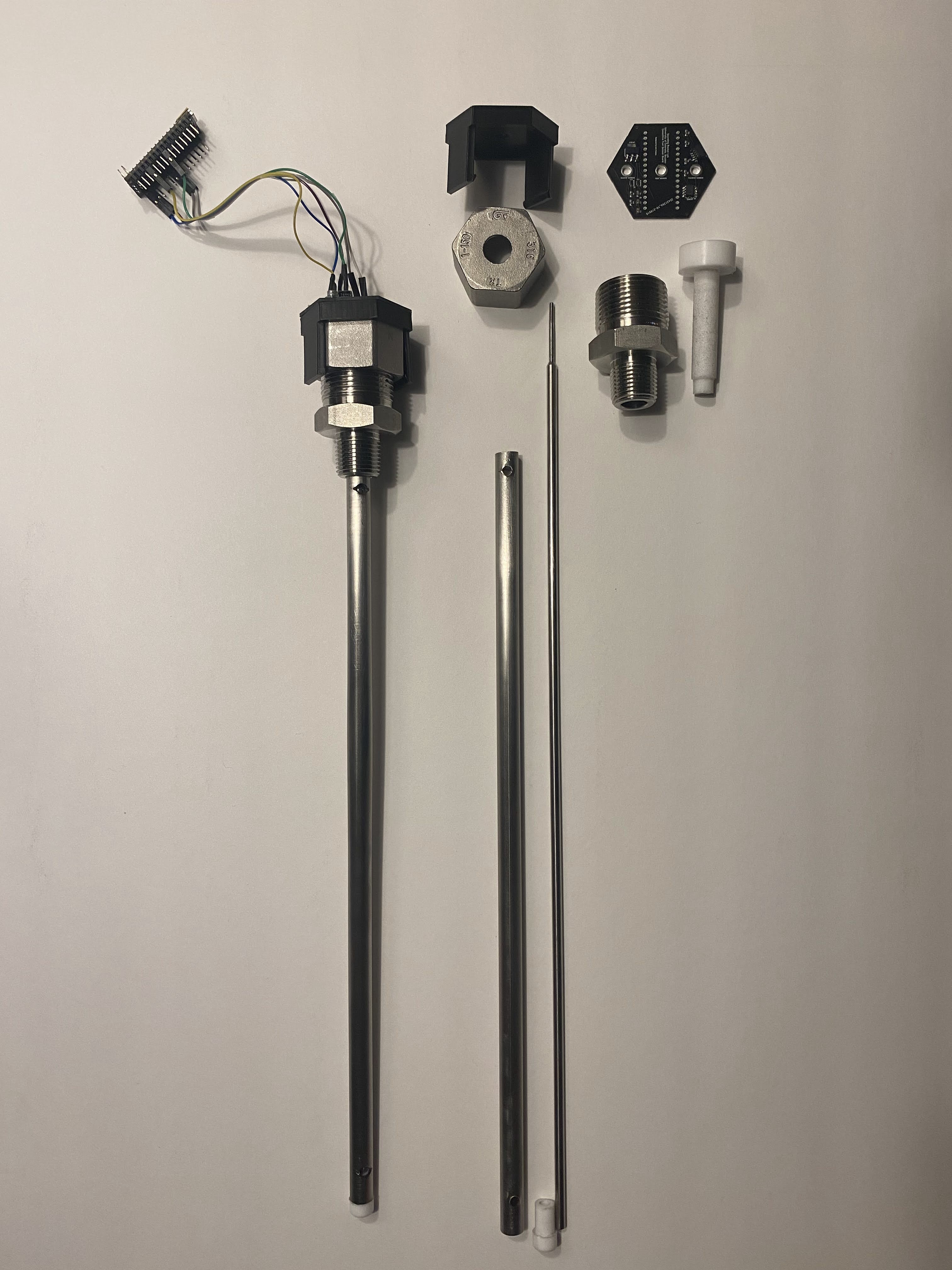
Implemented a capacitance-based concentric two-rod stainless-steel sensor with PTFE end caps for electrical isolation and high-pressure sealing. Used an Arduino Uno’s known internal trace capacitance to form a capacitor divider with the sensor, enabling consistent capacitance-to-height conversion and a filtered 0–5 V analog output proportional to tank fill level with optional I2C communication.

Technologies & Tools

C++ (Arduino) Embedded Electronics Signal Filtering SolidWorks Stainless/PTFE Fabrication Cryogenic Testing Test & Integration Design for Manufacturing
Sensor demonstration: capacitance-to-height readout behavior

Design & Development

Capacitive Sensing Principle

Two concentric electrically isolated stainless-steel rods form a capacitor. As liquid fills the annulus between the rods, the effective permittivity increases and the capacitance rises. This shift in capacitance is mapped to liquid height using the fluid’s properties and the sensor’s geometry.

  • Stainless concentric electrodes
  • PTFE end caps provide isolation and pressure passthrough
  • Capacitance range: ~36–58 pF in normal operation
  • Water testing observed ~2142 pF (high εr)
Capacitive sensor principle diagram showing concentric rods and fluid fill
Capacitive sensing principle: concentric-rod geometry and fluid fill region

Electronics & Readout

The Arduino’s internal trace capacitance forms a divider with the sensor. By charging the sensor rods and measuring the charged voltage over time can be used to calculate capacitance, which is then converted to fluid height. Height is output as a 0–5 V analog level or via I2C to the test stand.

  • Internal capacitance ≈ 30 pF (characterized for accuracy)
  • Resolution: ~1% for Propellant (3.5–225 pF); ~5% for DI Water (Up to 2 nF)
  • Minimum height resolution ≈ ±11.5 mm (total propogated error)
  • Optional parallel cap (~1250 pF) allows for easy conversion to water tests
Capacitor charge/discharge waveform illustrating capacitance-dependent timing
Charge/discharge behavior used to infer capacitance (and thus liquid height)
Sensor head with attached PCB shown outside the tank
Electronics PCB mounted at the sensor head for short, low-noise routing

Mechanical & Integration

The stainless/PTFE assembly was designed for high-pressure plumbing and cryogenic exposure. The analog 0–5 V and I2C outputs integrate directly with SRL’s DAQ for real-time level visualization and control logic.

  • Stainless-steel rods & tube for LOX compatibility and durability
  • PTFE dielectric and seals for isolation and electrical tank pass-through
  • Bench and water-flow calibration prior to stand integration
  • Compressed PTFE ensured liquid leak tight
Mechanical cross-section highlighting concentric electrodes and sealed pass-through
Mechanical details: concentric electrodes and sealed pass-through for tank integration

Technical Specifications

Measurement

Operating Capacitance: ~36–58 pF (LOX/RP-1)

Extended Range (water): ≈ 2.1 nF with parallel cap

Resolution: ~1% (3.5–225 pF), ~5% to 2 nF

Min Fluid Height Resolution: ±11.5 mm

Environment

Fluids: LOX, RP-1, water (for flow testing)

Conditions: Cryogenic-tolerant, high-pressure tank

Isolation: PTFE end-cap dielectric and electrical passthrough

Mechanical

Sensor Body: Concentric stainless rods

Dielectric/Seals: PTFE

Mounting: NPT threaded vertically into tank

Pressure: 1.6 structural FoS with 700 psi MEOP

Leakage: Verified acceptable leakage at 700 psi MEOP

Interface

Controller: Arduino Uno

Output: 0–5 V analog or I2C

Calibration: Characterizes fluid permittivity & sensor geometry

Results & Impact

±11.5 mm
Minimum height resolution
1% / 5%
Capacitance measurement accuracy
0–5 V
Simple analog level output

Key Achievements

Robust Cryo-Capacitive Design

Concentric stainless rods with PTFE isolation survived handling and plumbing for test-stand integration.

Direct DAQ Integration

Generated a filtered 0–5 V analog signal mapping 0–100% fill with optional I2C output simplifying stand operations.

Sensor Range Easily Extensible for Water Tests

Optional ~1250 pF parallel capacitor extended measurable range for high-εr water flow testing.

Lessons Learned

Characterizing the Arduino’s internal capacitance is critical for accuracy and is not consistent across different chips. This should be calibrated independently for each sensing device. Fluid permittivity changes and temperature effects drive the need for fluid-specific calibration. Cleanliness of system must be maintained for LO2 compatibility and to ensure testing DI water remains non-conductive.

Future Work

Add temperature compensation, implement a dedicated capacitance-to-digital converter for higher resolution, and perform full cryogenic calibration with LOX and RP-1 to refine height mapping across operating conditions instead of solely using DI Water.

Project Gallery

Let's Connect

I'd be happy to discuss my experience in more detail or explore potential career opportunities.

Copied to Clipboard